Not Gate Diagram
Gate circuit diagram input power through circuitdiagram button explanation connected then What is a not gate? Gate configuration ic logic pinout gates truth table input inversion shows figure
LOGIC GATES | NOT Gate | NAND Gate | NOR Gate | Universal Gates
Gate 7404 circuit ic diagram gates led used vcc input using output part arduino make ground timer electronics funny cube Gate not circuit diagram transistor electrical4u principle working Not gate circuit diagram and working explanation
What are logic gates? or, and, not logic gate with truth table
Nand xor logic nor gates xnor circuit vhdl simulate verify truth input circuits tutorial engineersgarage inverter scosche inputs ckt combinedVhdl tutorial – 5: design, simulate and verify nand, nor, xor and xnor Not gate: how does it work? (circuit diagram & working principleElectrical symbols — logic gate diagram.
Gate circuit switching switch open logic symbol lamp when will glow illustrates go off figureLogic gates Gate diagram logic not electrical stencils library vector inverter symbolsCircuit nor gate diagram working circuits explanation resistors electronic integrated chosen necessary pull down these.
Nor gate circuit diagram & working explanation
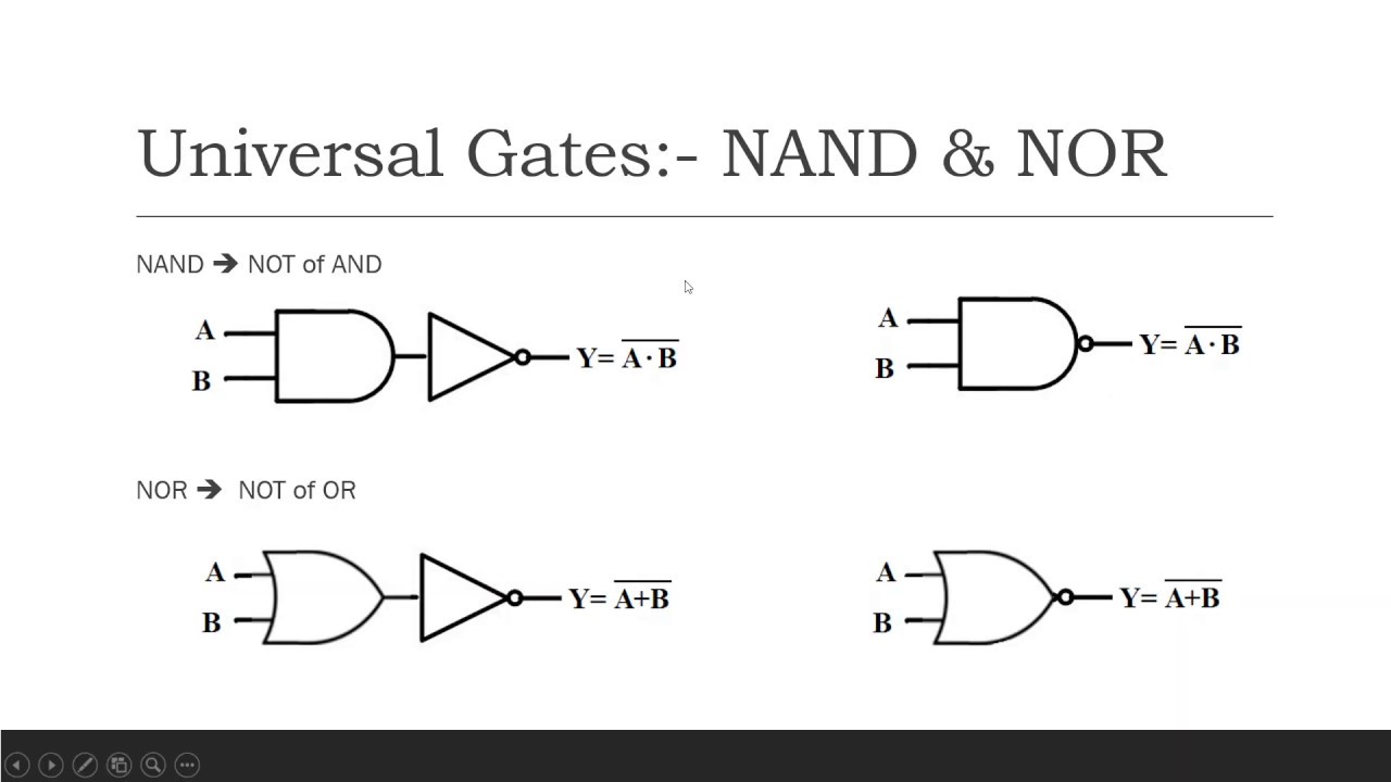
Animated 555 circuit to make patterns in 3*3*3 led cube (part 1Nand nor explanation .
.

-logic-gate-diagram---vector-stencils-library.png--diagram-flowchart-example.png)
Electrical Symbols — Logic Gate Diagram | 2-bit ALU - Logic gate

What is a NOT Gate? - Logic Symbol & Truth Table - Circuit Globe

NOT Gate: How Does it Work? (Circuit Diagram & Working Principle

Animated 555 Circuit to Make Patterns in 3*3*3 LED Cube (Part 1

NOT Gate Circuit Diagram and Working Explanation

VHDL Tutorial – 5: Design, simulate and verify NAND, NOR, XOR and XNOR

What are Logic gates? OR, AND, NOT logic gate with truth table